Table of Contents
This guide examines hook type shot blasting machine capacity for applications involving weldments and large castings. The review focuses on fixture orientation and all-face coverage, with a clear distinction between an attractive demonstration and evidence that supports the required production result. The following sections address the actual decisions involved in capacity and line balancing: the limiting feature, material and handling conditions, relevant measurements and questions that need a supplier answer before the configuration or supply specification is accepted.
Hook type shot blasting machine capacity: define the output denominator
Inspect the part in its actual hanging orientation and after unloading; photographs of an empty hook do not demonstrate coverage. Choose accepted components, accepted mass or prepared area as the output measure. Keep rejected and reworked items visible. An hourly figure based on everything leaving the chamber can overstate useful output when some parts need another pass or fail inspection.
Record the fixture drawing and part orientation with the accepted result rather than relying on a photograph of the bare machine. The evidence for hook type shot blasting machine capacity should make fixture orientation and all-face coverage verifiable under the accepted operating condition. Use the same acceptance requirement and output unit in every comparison.
Determine usable loading
For hook type shot blasting machine capacity, a suspended casting rotates with its fixture; the fixture and adjacent parts can shield surfaces even while the hook is moving normally. Measure the approved load by its actual arrangement as well as its mass. Check whether components turn, remain spaced or expose required faces. A chamber volume or lifting limit is a constraint, not proof that every load up to that limit produces acceptable output.
Trace the stream around the actual fixture; continuous hook rotation cannot expose a face permanently shielded by the hanger assembly. The hook type shot blasting machine capacity review should preserve the limiting application case: an irregular casting with a sheltered pocket. Record the load arrangement that produced the accepted result and preserve its limiting feature.
Time the complete transfer sequence
Include fixture mass, center of gravity, travel clearance and the intended rotation arrangement in the hanging-load review. Start timing at a defined ready-to-load condition and stop at the corresponding ready-for-next-operation condition. Separate loading, treatment, draining, unloading and inspection. Do not add overlapping activities twice, and do not omit a handling delay simply because it occurs outside the chamber.
The fixture consumes lifting allowance and chamber space; include both before comparing a component mass with a model limit. Show the intended suspended rotating load arrangement in the hook type shot blasting machine capacity evidence rather than leaving it as an unstated assumption. Draw the cycle timeline and identify the longest non-overlapping sequence.
Establish exposure from quality
Deep pockets and flange roots can remain dull with scale while exposed outer edges already show excessive impact. Use the treatment time or conveyor setting that meets the surface requirements on the difficult feature. A faster setting has no capacity value when it produces rejectable work. Compare exposed and shielded areas so an adjustment does not trade one quality problem for another.
Compare a flange root with an exposed edge so a longer cycle does not disguise shadowing by damaging the open geometry. For hook type shot blasting machine capacity, retain the required location-specific results for applications involving weldments and large castings. Do not extrapolate accepted throughput from the fastest demonstrated mechanical movement.
Check media supply over consecutive loads
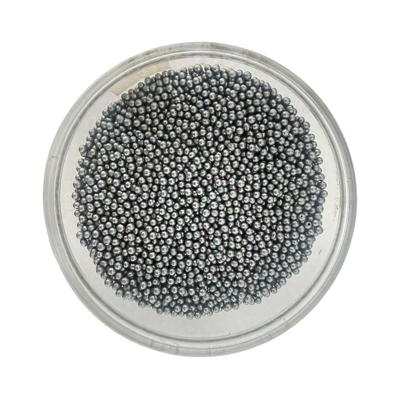
For hook type shot blasting machine capacity, the selected abrasive must leave the hanging component without collecting in upward-facing pockets or overlapping welded features. Observe the working charge, feed behavior and replenishment during successive normal loads. A brief run with a fresh charge may hide an instability that reduces accepted output later. Keep changes in abrasive condition separate from changes in the component or handling pattern.
Check upward-facing pockets before unloading, because reusable shot can leave a suspended casting after the treatment already appears complete. Document the accepted material condition used in the hook type shot blasting machine capacity comparison, including the relevant delivery identity and working state. Tie the output observation to the working-media state that supported it.
Test recovery and discharge interruptions
A drain or reorientation step may be needed before the hook leaves the chamber; shot carried into unloading is a measurable loss route. Include the operating activities needed to keep the circuit running: rejected-material removal, usable-media return and routine replenishment. A production estimate that assumes these tasks never interrupt work needs evidence from the actual arrangement.
Observe the approved draining position and the material falling at unloading to separate carryout from internal breakdown. Trace usable and rejected material over the same operating boundary when evaluating hook type shot blasting machine capacity. Distinguish designed overlap from a task that requires an authorized production stop.
Account for availability without double counting
Inspect hook and fixture wear, local chamber liners and the sealing arrangement at the entry path according to the equipment procedure. Keep planned service, changeovers and unplanned stops separate from the measured production cycle. Apply an availability allowance only to the time not already included. Multiplying by an arbitrary utilization factor can conceal the actual source of downtime and make a comparison impossible to improve.
A local liner impact zone may reveal a changed presentation or stream direction and should be compared with the hanging arrangement. The hook type shot blasting machine capacity decision should connect the observed condition with the actual production duty and relevant inspection location. Use observed plant duty or an explicitly stated planning assumption for the available-time calculation.
Check the line bottleneck
For hook type shot blasting machine capacity, q37 catalogue lifting capacities apply to specified models; the exact lifting arrangement and approved fixture remain part of the inquiry. Compare the accepted machine output with loading supply and the downstream station. A faster cleaning machine can create queues instead of more shipped product. State the assumed staffing, incoming work mix and available shift time alongside the calculated rate.
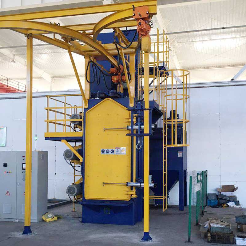
Confirm the actual suspended assembly for the selected model, including its center of gravity and the supplier-approved movement arrangement. For a hook type shot blasting machine capacity inquiry, confirm the specific supplied configuration or grade and the requirements that remain application-dependent. The practical capacity is the accepted flow that the complete production route can sustain.
Illustrative complete-cycle calculation
Consider an assumed batch containing 80 components. Loading takes three minutes, accepted treatment takes eight minutes and unloading plus the required inspection takes five minutes, with no overlap between these activities. The complete cycle is therefore 16 minutes, giving 300 components per hour before a quality allowance. At an assumed 96% first-pass acceptance, the useful rate is 288 accepted components per hour. These assumed figures explain the method; they are not a model specification or customer result for hook type shot blasting machine.
A second arrangement that reduces non-overlapping handling by two minutes would need a fresh calculation and a verification of the same accepted surface result. Do not claim the improvement from the treatment time alone. For weldments and large castings, record the actual approved load and the limiting feature in an irregular casting with a sheltered pocket. If a second hook, automatic loader or different fixture enables genuine overlap, draw the revised timeline so that an activity is neither omitted nor counted twice.
Comparison of useful and incomplete evidence
| Review item | Useful evidence | Incomplete basis |
|---|---|---|
| Define the output denominator | Inspect the part in its actual hanging orientation and after unloading; photographs of an empty hook do not demonstrate coverage. Use the same acceptance requirement and output unit in every comparison. | A general statement without the relevant application condition, measurement or configuration. |
| Time the complete transfer sequence | Include fixture mass, center of gravity, travel clearance and the intended rotation arrangement in the hanging-load review. Draw the cycle timeline and identify the longest non-overlapping sequence. | A general statement without the relevant application condition, measurement or configuration. |
| Check media supply over consecutive loads | The selected abrasive must leave the hanging component without collecting in upward-facing pockets or overlapping welded features. Tie the output observation to the working-media state that supported it. | A general statement without the relevant application condition, measurement or configuration. |
| Account for availability without double counting | Inspect hook and fixture wear, local chamber liners and the sealing arrangement at the entry path according to the equipment procedure. Use observed plant duty or an explicitly stated planning assumption for the available-time calculation. | A general statement without the relevant application condition, measurement or configuration. |
For relevant background, consult Wikipedia’s overview of abrasive blasting. The background reference explains abrasive-cleaning terminology. It is not a product certificate or an application acceptance report.
Discuss the application with Dazheng
Use the Q37 Series Hook-Type Shot Blasting Machine information to start the inquiry. Send the material, drawing, incoming condition, required result and production duty for weldments and large castings. Explain the limiting case: an irregular casting with a sheltered pocket. Ask how fixture orientation and all-face coverage will be verified. Confirm exact configuration or material availability, utilities, support scope and acceptance evidence before treating a general listing as a complete proposal.
Frequently asked questions
What should be specified first for hook type shot blasting machine capacity?
Choose accepted components, accepted mass or prepared area as the output measure. Keep rejected and reworked items visible. An hourly figure based on everything leaving the chamber can overstate useful output when some parts need another pass or fail inspection. Inspect the part in its actual hanging orientation and after unloading; photographs of an empty hook do not demonstrate coverage.
Which evidence matters most when reviewing hook type shot blasting machine capacity?
Draw the cycle timeline and identify the longest non-overlapping sequence. Include fixture mass, center of gravity, travel clearance and the intended rotation arrangement in the hanging-load review.
Can a catalogue description settle a hook type shot blasting machine capacity decision?
A catalogue identifies a product family. Q37 catalogue lifting capacities apply to specified models; the exact lifting arrangement and approved fixture remain part of the inquiry. Ask for the exact configuration or material confirmation and the agreed application evidence.
How should a changed hook type shot blasting machine arrangement be checked?
Inspect the part in its actual hanging orientation and after unloading; photographs of an empty hook do not demonstrate coverage. Keep the change, operating conditions and required acceptance results traceable before extending approval.
What belongs in the technical inquiry for hook type shot blasting machine capacity?
Provide the component material, dimensions, incoming condition, required result and production duty. The practical capacity is the accepted flow that the complete production route can sustain. Include drawings or photographs of the limiting feature.