Table of Contents
Introduction
A shot blasting machine diagram is more than a simple equipment sketch. For operators, engineers, maintenance teams, and equipment buyers, it provides a clear way to understand how the blasting chamber, blast wheel, abrasive recovery system, separator, dust collector, workpiece handling mechanism, and control system work together.
Industrial shot blasting equipment operates as an integrated circulation system. Abrasive must be stored, supplied to the blast wheel, accelerated toward the workpiece, recovered after impact, separated from contaminants, and returned for reuse. At the same time, dust generated during cleaning must be extracted and filtered.
Understanding a shot blasting machine diagram makes it easier to locate these systems, identify wear-prone components, recognize material flow, and understand why different machine configurations require different layouts. This guide explains the major sections of a typical wheel-blast machine and how each component contributes to reliable surface cleaning.
Understanding a Basic Shot Blasting Machine Diagram
A typical shot blasting machine can be divided into several functional zones rather than viewed as one enclosed cabinet.
The first is the workpiece handling zone, where components enter, rotate, tumble, hang, or move through the machine. The second is the blasting zone, where blast wheels project abrasive onto the exposed surfaces.
Below and around the blasting chamber is the abrasive recovery system. Used media and removed contaminants are collected and transported toward the elevator and separator. Reusable abrasive then returns to the storage hopper.
A separate air-handling path connects the machine to a dust collector. This system removes fine airborne particles generated during blasting and separation.
A simplified shot blasting machine diagram can therefore be represented as:
Abrasive Hopper → Abrasive Control Valve → Blast Wheel → Workpiece Surface → Recovery Conveyor → Bucket Elevator → Separator → Abrasive Hopper
At the same time:
Blast Chamber / Separator → Dust Duct → Dust Collector → Filtered Air
These two circulation paths—abrasive flow and airflow—operate simultaneously during production.
Main Components Shown in a Shot Blasting Machine Diagram
Although exact layouts differ between crawler, hook, conveyor, and mesh belt equipment, most industrial wheel-blast systems contain several common components.
| Component | Main Function |
|---|---|
| Blast chamber | Contains the blasting operation |
| Blast wheel | Accelerates abrasive toward the workpiece |
| Abrasive hopper | Stores reusable blasting media |
| Abrasive valve | Controls media flow to the blast wheel |
| Recovery conveyor | Collects and transports used abrasive |
| Bucket elevator | Lifts recovered abrasive to the separator |
| Separator | Removes dust and contaminants from reusable media |
| Dust collector | Extracts and filters airborne particles |
| Workpiece handling system | Moves or rotates components during blasting |
| Wear liners | Protect high-impact areas of the machine |
| Electrical control system | Coordinates machine operation and safety functions |
These components form the basic framework of most shot blasting equipment even when the overall machine shape changes.
Blast Chamber
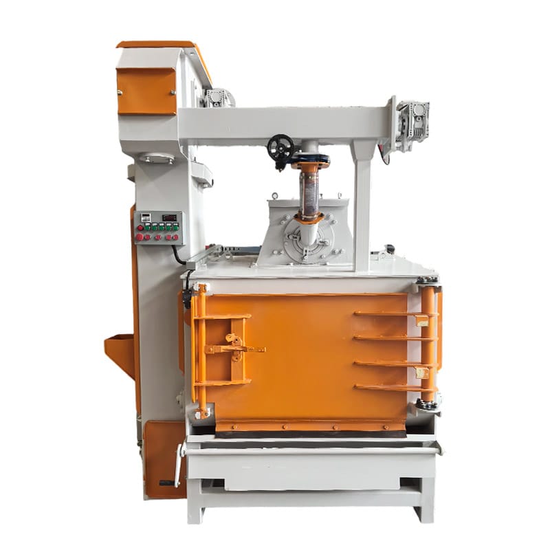
The blast chamber is the enclosed area where abrasive strikes the workpiece.
Its primary function is containment. High-speed abrasive must remain inside a protected space while the workpiece is being cleaned. The chamber therefore needs sufficient structural strength and internal wear protection.
Direct abrasive impact can gradually erode exposed surfaces. For this reason, critical areas are normally protected by replaceable wear-resistant liners.
The internal layout of the chamber depends on machine type. A crawler machine requires space for the moving belt and tumbling workpieces. A hook machine needs clearance for suspended components to rotate. A pass-through machine requires inlet and outlet openings that allow long workpieces to travel through the blasting zone.
When interpreting a shot blasting machine diagram, the chamber should therefore be considered the central working area around which the remaining systems are arranged.
Blast Wheel Assembly
The blast wheel is the primary component responsible for generating cleaning energy.
Abrasive enters the wheel and is accelerated by rapidly rotating blades. The resulting abrasive stream leaves the wheel in a controlled direction and strikes the workpiece.
Important blast wheel components can include the wheel blades, impeller, control cage, housing, motor, and abrasive feeding arrangement.
The blades experience continuous abrasive contact and are therefore wear components. The control cage and impeller also influence how abrasive enters and leaves the wheel.
Blast wheel orientation is equally important. A wheel installed in the wrong position may direct too much abrasive toward one area while leaving another section insufficiently treated.
In larger machines, several blast wheels may be positioned above, below, or beside the workpiece path to improve surface coverage.
Abrasive Storage Hopper
The abrasive storage hopper is usually positioned above or near the blasting system so reusable media can be supplied continuously to the blast wheels.
Its function is relatively simple but important: maintain a sufficient reserve of clean abrasive for stable operation.
If the hopper level becomes too low, abrasive flow to the wheel may become inconsistent. This can reduce impact density and affect surface cleaning.
The hopper is connected to abrasive control devices that regulate the amount of media entering the wheel.
A stable blasting process depends on keeping this supply consistent rather than allowing large variations in abrasive flow during each production cycle.
Abrasive Control Valve
The abrasive control valve regulates how much media moves from the storage hopper toward the blast wheel.
Too little abrasive can reduce cleaning performance. Excessive abrasive can overload the wheel, recovery system, or separator without producing a proportional improvement in surface quality.
The correct abrasive flow depends on wheel design, motor power, workpiece condition, media characteristics, and required cleaning performance.
Modern systems may connect abrasive flow control with the electrical control system so media is supplied only when the blast wheel and workpiece handling system are operating under appropriate conditions.
In a shot blasting machine diagram, this valve is usually positioned between the abrasive storage section and the blast wheel feed line.
Workpiece Handling System
The workpiece handling mechanism is one of the main features that distinguishes different machine types.
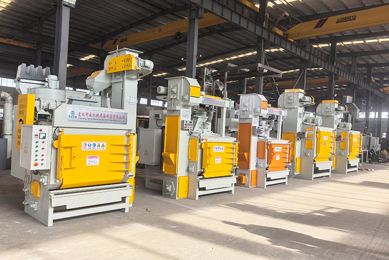
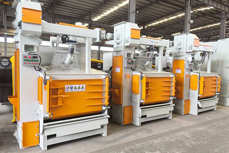
A crawler-type shot blasting machine uses a moving belt to tumble suitable components through the blast zone. Different surfaces become exposed as the parts continuously change position.
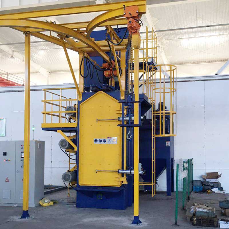
A hook-type shot blasting machine suspends workpieces from a hook and rotates them inside the chamber. This arrangement is useful when components are larger, irregular, or unsuitable for tumbling.
Pass-through machines use roller conveyors or other transport systems to carry workpieces through the chamber. Mesh belt equipment supports parts on a continuous belt.
This means two shot blasting machine diagrams may look very different even though the abrasive circulation systems are based on the same principles.
Recovery Hopper and Lower Collection Area
After abrasive strikes the workpiece, gravity carries the used media downward.
The abrasive is now mixed with rust, scale, casting residue, broken media, and other contaminants removed from the surface.
The lower section of the machine collects this mixture and directs it toward the recovery conveyor.
The design must minimize areas where abrasive can accumulate unnecessarily. Dead zones can interfere with media circulation and make cleaning or maintenance more difficult.
This area also experiences considerable abrasion because large quantities of media continuously pass through it.
Wear-resistant protection and convenient inspection access are therefore important design considerations.
Screw Conveyor
Many shot blasting machines use screw conveyors to move recovered abrasive horizontally toward the bucket elevator.
A rotating screw transports the mixture along an enclosed trough. The system is compact and can handle continuous abrasive flow effectively when properly maintained.
Because the conveyor remains in frequent contact with abrasive, flights, shafts, bearings, seals, and trough protection should be inspected regularly.
Abnormal noise or reduced recovery performance can indicate wear, obstruction, or mechanical damage.
The screw conveyor may appear near the bottom of a shot blasting machine diagram, where it connects the blast chamber recovery area to the vertical elevator system.
Bucket Elevator
The bucket elevator transports recovered abrasive vertically from the lower recovery system to the upper separator.
A series of buckets attached to a moving belt or chain collects abrasive at the bottom and lifts it toward the top of the machine.
This vertical transport stage is essential because the separator and storage hopper are commonly positioned above the blast wheels.
Bucket condition, belt tension, alignment, drive components, and discharge performance should be monitored. Damage or poor adjustment can reduce abrasive circulation and eventually affect cleaning consistency.
When operators experience irregular abrasive supply, the recovery and elevator systems should be inspected rather than assuming the problem originates only at the blast wheel.
Abrasive Separator
The separator is one of the most important sections shown in a shot blasting machine diagram.
Recovered abrasive cannot immediately return to the blast wheel because it contains rust, scale, dust, broken abrasive, and other contaminants.
The separator removes unwanted material while retaining usable abrasive.
Effective separation helps maintain a more stable operating mix. If excessive dust or broken particles return to the blasting circuit, cleaning behavior can change and component wear may increase.
At the same time, the separator should avoid unnecessarily discarding usable abrasive.
Separator performance therefore influences both surface consistency and media consumption.
Abrasive Circulation Path
The complete abrasive circulation path connects several components into one continuous loop.
The cycle normally follows this sequence:
Storage Hopper → Abrasive Valve → Blast Wheel → Workpiece → Recovery System → Screw Conveyor → Bucket Elevator → Separator → Storage Hopper
This circulation repeats continuously while the equipment operates.
The concept is part of the wider family of abrasive blasting, although wheel-blast machines use centrifugal wheels rather than compressed-air nozzles to accelerate the media.
Understanding the circulation path is particularly useful for troubleshooting. If abrasive supply becomes unstable, operators can inspect each stage of the loop instead of focusing only on the blast wheel.
Dust Collection System
A shot blasting machine diagram should also show the dust extraction path.
Surface cleaning generates fine particles from rust, scale, casting residue, broken abrasive, and other contaminants. These particles become suspended in the airflow inside the chamber and separator.
Ductwork connects the equipment to a dust collector, which draws contaminated air from the machine.
Inside the collector, filters capture fine particles before cleaned air is handled according to the system design.
Adequate airflow helps maintain cleaner internal conditions and supports abrasive separation. Insufficient extraction can allow excessive fines to remain inside the system.
Dust collector performance should therefore be considered part of the blasting process rather than a separate accessory.
Cartridge Dust Collector Components
Where cartridge filtration is used, the dust collector normally contains filter cartridges arranged inside a sealed housing.
Dust-laden air enters the collector and passes through the filter media. Fine particles remain on the filter surface while cleaner air passes through.
As dust accumulates, a cleaning mechanism removes material from the filters so airflow can be maintained. Collected dust falls into a lower hopper for disposal.
Pressure difference across the filters can provide useful information about operating condition. An unusually high pressure differential can indicate excessive dust loading or restricted airflow.
Filter inspection, pulse-cleaning performance, seals, ducts, and dust discharge components should therefore form part of routine maintenance.
Wear-Resistant Liners
Wear liners protect machine surfaces exposed to repeated abrasive impact.
The blasting chamber receives millions of abrasive impacts during normal production. Without replaceable protection, structural steel sections of the machine would experience accelerated wear.
Liners are generally installed around high-impact zones, especially where the blast pattern strikes chamber walls after passing the workpiece.
Wear is not always uniform. Areas close to the main blast pattern can deteriorate much faster than locations receiving indirect abrasive contact.
Regular inspection is important because continuing operation after a liner has worn through can transfer damage to more expensive structural components.
For maintenance planning, wear liners should therefore be identified clearly in the equipment layout.
Entry and Exit Sealing Systems
Pass-through equipment requires openings for plates, beams, profiles, or other workpieces to enter and leave the blasting chamber.
These openings create a containment challenge because abrasive must remain inside the machine while the workpiece continues moving.
Sealing systems may use curtains, brushes, chambers, or multiple containment stages to reduce abrasive escape.
The design depends on workpiece dimensions, conveyor configuration, blasting intensity, and machine layout.
Worn seals can lead to abrasive leakage around the inlet or outlet. This creates housekeeping problems and indicates that inspection or replacement may be needed.
Crawler and hook machines use different door or chamber sealing arrangements because they normally operate with closed access during blasting.
Electrical Control System
The electrical control system coordinates the mechanical and safety functions of the machine.
Typical controls can manage blast wheel motors, conveyors, elevators, workpiece handling, abrasive valves, dust extraction, and sequence timing.
Interlocks are important because certain systems must operate in the correct order. For example, abrasive should not normally be supplied to a blast wheel that has not reached the intended operating condition.
The control system can also respond to overloads, abnormal motor conditions, or other detected faults.
Automation level varies by machine configuration. A relatively simple batch machine may require fewer control functions than a pass-through system integrated into a continuous production line.
Crawler-Type Shot Blasting Machine Layout
In a crawler machine, the diagram is centered around a chamber containing a continuous belt.
The workpieces are loaded onto the crawler. As the belt moves, the parts tumble while one or more blast wheels direct abrasive toward them.
Used abrasive falls beneath the crawler into the lower recovery section.
The media then passes through the conveyor, elevator, separator, and storage hopper before returning to the wheel.
This configuration is compact because workpiece movement occurs inside the same enclosed chamber.
The design is particularly effective for batches of robust parts capable of tumbling without unacceptable damage.
Hook-Type Shot Blasting Machine Layout
A hook machine diagram has a different workpiece-handling arrangement.
The workpiece is suspended from an overhead hook and moved into the blasting chamber. During the cycle, the hook rotates so different surfaces become exposed to the abrasive stream.
Blast wheels are positioned around the chamber according to workpiece geometry and required cleaning coverage.
Abrasive falls to the recovery system below the suspended load and follows the same general circulation route through conveying, elevation, separation, and storage.
The suspended arrangement makes the machine suitable for workpieces that should not tumble against each other.
Pass-Through Machine Layout
Pass-through equipment uses a longer horizontal layout because the workpiece continuously travels through the machine.
A loading conveyor leads into the blasting chamber. Several blast wheels may be arranged above, below, or beside the conveyor path.
After blasting, the workpiece travels through an exit section before reaching the unloading conveyor.
Beneath the chamber, abrasive recovery systems collect media across the length of the blasting zone.
This configuration allows surface preparation to become part of a continuous production line.
Because multiple systems operate simultaneously, the machine diagram is especially useful for understanding material flow, wheel locations, abrasive circulation, and dust extraction.
Reading a Shot Blasting Machine Diagram for Maintenance
Maintenance teams can use equipment diagrams to trace problems more efficiently.
If abrasive is not reaching the blast wheel consistently, inspection can begin at the storage hopper and continue through the control valve, feed pipe, separator, elevator, and recovery system.
If cleaning becomes uneven, the blast wheel, wear components, abrasive pattern, and workpiece handling system should be examined.
If dust concentration increases, the ductwork, filter system, collector, separator, and chamber seals can be checked.
The diagram therefore helps operators understand cause-and-effect relationships between components.
This approach is more effective than replacing individual parts without considering how the entire machine operates as a connected system.
Key Wear Areas to Identify on the Diagram
Several machine areas should receive particular attention because abrasive wear is inherent to shot blasting.
Blast wheel blades, impellers, control cages, chamber liners, abrasive valves, screw conveyors, elevator buckets, seals, and recovery sections all handle abrasive directly.
Wear rate depends on operating hours, abrasive type, abrasive size, machine configuration, blast intensity, and maintenance practices.
Operators should establish inspection intervals based on actual equipment conditions rather than waiting for visible failure.
Unexpected increases in vibration, noise, abrasive leakage, media consumption, or cleaning inconsistency can indicate that a wear component requires attention.
Why Equipment Layout Matters for Machine Selection
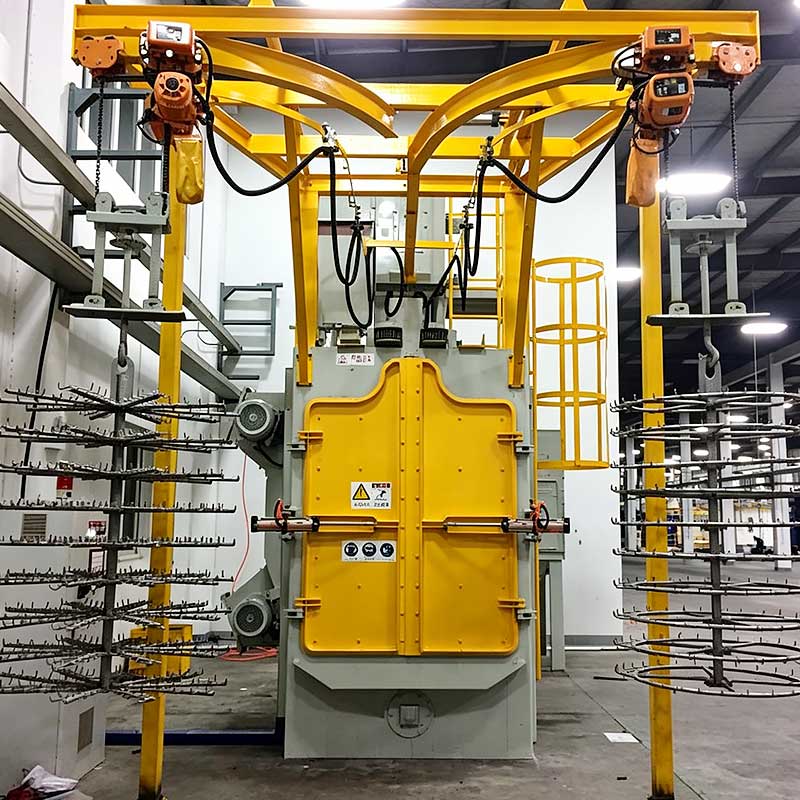
A shot blasting machine diagram can also help buyers compare equipment before installation.
Machine dimensions alone do not show how material moves through the equipment or how maintenance access is arranged.
Buyers should examine loading direction, workpiece movement, blast wheel locations, recovery system arrangement, dust collector connection, service access, and abrasive handling.
Factory layout also matters. Hook systems may require overhead lifting access, while long pass-through machines need sufficient floor space for loading and unloading conveyors.
Crawler equipment can be more compact but requires a suitable method for batch loading and unloading.
Reviewing these relationships early can reduce installation and production-flow problems later.
Conclusion
A shot blasting machine diagram provides a practical way to understand how the main mechanical, abrasive, and air-handling systems interact.
The blast chamber contains the cleaning operation, while the blast wheel accelerates abrasive toward the workpiece. Recovery conveyors and elevators transport used media to the separator, where reusable abrasive is cleaned and returned to the storage hopper. Dust collection operates alongside this circulation loop to remove airborne fines.
Different machine types change the workpiece-handling section of the diagram, but the core relationship between blasting, recovery, separation, reuse, and dust extraction remains consistent.
Understanding this layout helps operators troubleshoot problems, maintenance teams identify wear areas, and equipment buyers evaluate whether a machine configuration matches their production requirements.
FAQ
What are the main parts shown in a shot blasting machine diagram?
A typical diagram includes the blast chamber, blast wheel, abrasive hopper, control valve, recovery conveyor, bucket elevator, separator, dust collector, wear liners, and workpiece handling system. These components work together to accelerate, recover, clean, and continuously recirculate abrasive during surface treatment.
Where does abrasive go after it hits the workpiece?
After impact, abrasive falls into the lower recovery section with rust, scale, dust, and other contaminants. Conveyors move the mixture to a bucket elevator, which lifts it to the separator. Reusable abrasive then returns to the storage hopper while unwanted material is removed from circulation.
Why is the separator important in the machine layout?
The separator prevents excessive dust, broken abrasive, scale, and other contaminants from returning to the blast wheel. Maintaining cleaner reusable media supports stable abrasive flow and more consistent surface treatment while reducing the amount of unsuitable material circulating through wear-sensitive machine components.
How does a crawler machine diagram differ from a hook machine diagram?
A crawler machine contains a moving belt that tumbles parts inside the chamber, while a hook machine suspends and rotates workpieces from an overhead handling system. Their abrasive recovery and separation systems are broadly similar, but the workpiece movement and chamber arrangements are significantly different.
How can a shot blasting machine diagram help with maintenance?
A diagram helps maintenance teams trace abrasive flow, locate wear components, and understand how one system affects another. When cleaning quality, abrasive supply, dust extraction, or machine movement becomes unstable, the layout provides a logical path for inspecting the relevant components instead of troubleshooting randomly.